
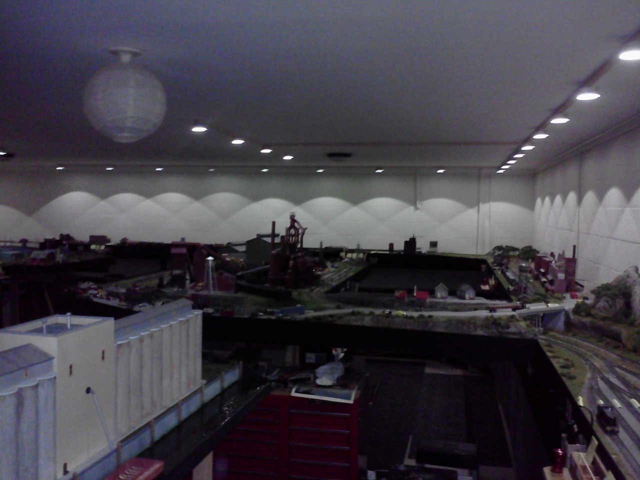
 When the lighting was first setup in the railroad room the lights were just seven 75w bulbs. With that much light in one spot the railroad was dark in several places. The lights were too bright to the eyes. The lights were changed to 25w compact fluorescent bulbs to cut the intensity, but it was still hard on the eyes. Chinese lantern covers were installed to deflect the light so it was not as bad on the eyes. This worked for a while with the use of flashlights in hand to see the train cars on the railroad. When you wanted to switch the cars, a flashlight was used to find the coupler to disconnect between the two cars. Something had to be done and in a way that it would not disturb the railroad. The lights were then changed to seven 18w LED flat mount light fixtures and the problem with the intensity went away.
I worked on many different ways to light the room and came up with a way to see all around the room with plenty of light. I wanted to find a way that would not take up much power and would keep the construction dirt down. To light the rest of the room I used 3w LED bulbs in cat food cans powered by a small 12v charger. Experiment was needed to find a balance to the lighting that was produced out of the cans. I took a can and added two sticks that were three feet long and glued them from the center of the can out to the opposite sides of the can to see the pattern that the light would make on the layout.
Click on the photo to enlarge it.

At first I was told that the LED would need a big heat sink because of the heat that it puts out. This is a cat food can with the center cut out so the LED would sit on the large plate and 3w LED light could transfer the heat on to the plate instead of the can. The large plate on the back is not going to be used as a heat sink and the can was replaced with a new one. It took only one test to show that it was not necessary because the heat sink on the back of the LED was more than enough to take away the heat from the LED. I used a hot glue gun to mount the LED in the can. Next was to find a way to run the power into the can. I drilled out two holes in the can larger than the wire being used to feed the wires under the can to hide them.
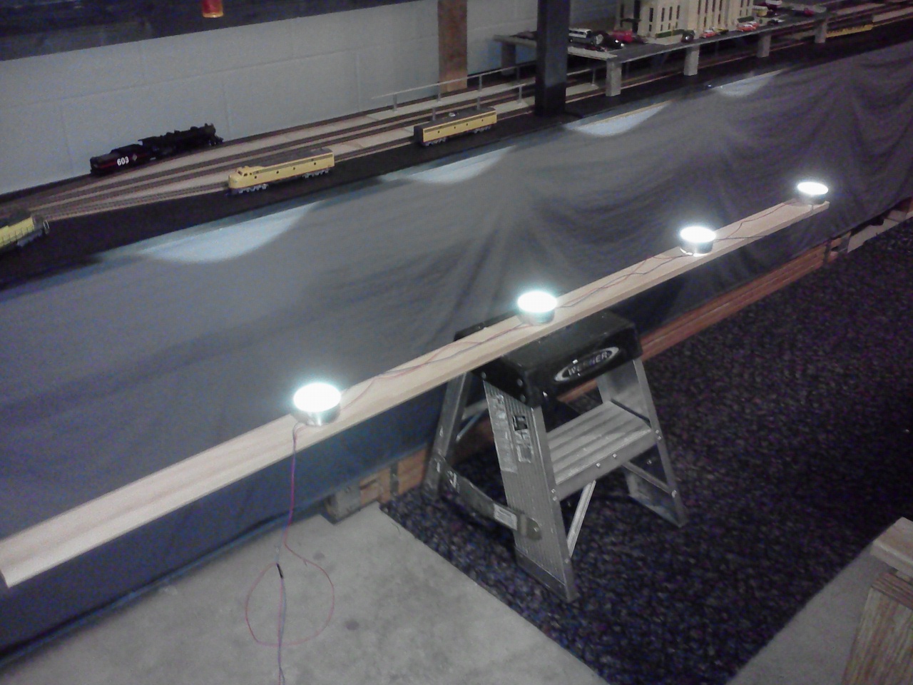
The drivers would Light up four lights in a series circuit and four sets of series circuits putting them in a parallel circuit. On a 1×4 board the LED lights were set up to make a test on the distance between the lights. I divided the distance on the board in to equal parts between the lights for this test. I took the can with the wood sticking out of it and checked it on the table top. I held the board up and developed a look that passed my inspection. I just needed to make it easier to mount on the ceiling.
The 1×4 board was cut into three strips with two grooves cut in the back of the strips to hold the wires out of the way. Extra wires were added to the center strips for the connections on the parallel circuits to carry the wires back to the driver. This let me take four sets of parallel lights and mount them together over the railroad and light one whole side up using four sections.
With all the other lights turned off, the lights were turned on to see the pattern on the railroad surface. The overlap of light made a pattern that had three lights shinning on the layout everywhere you looked. I looked for any spots on the railroad to see if the couplers were shaded and unable to be seen. I had other railroaders come and do a test on the lighted end of the railroad. I’m here to say it passed with flying colors. It took several friends to help put up and wire up the lights.
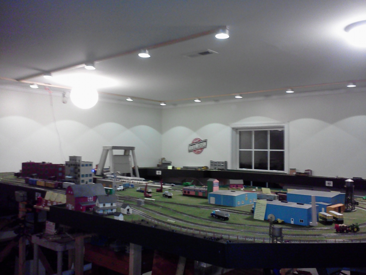
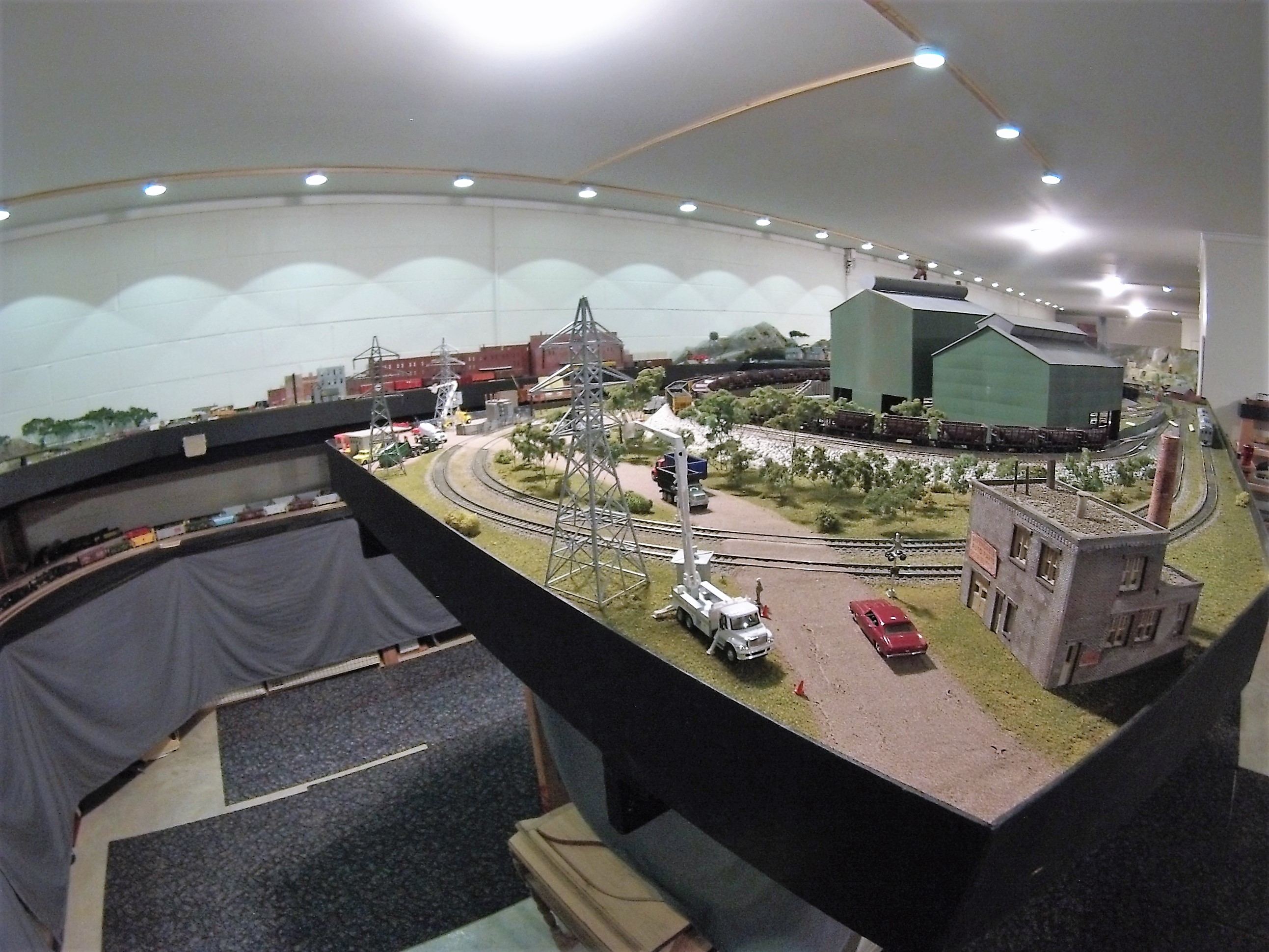
Another shot of the railroad from a different angle. Two sets of buck drivers are running the lights in this photo. The railroad was divided into four sections on the ceiling. One was added to the underside of the layout to light up the station. One driver is set up under the layout to do this. The future plan is to run lights on the lower level tracks.
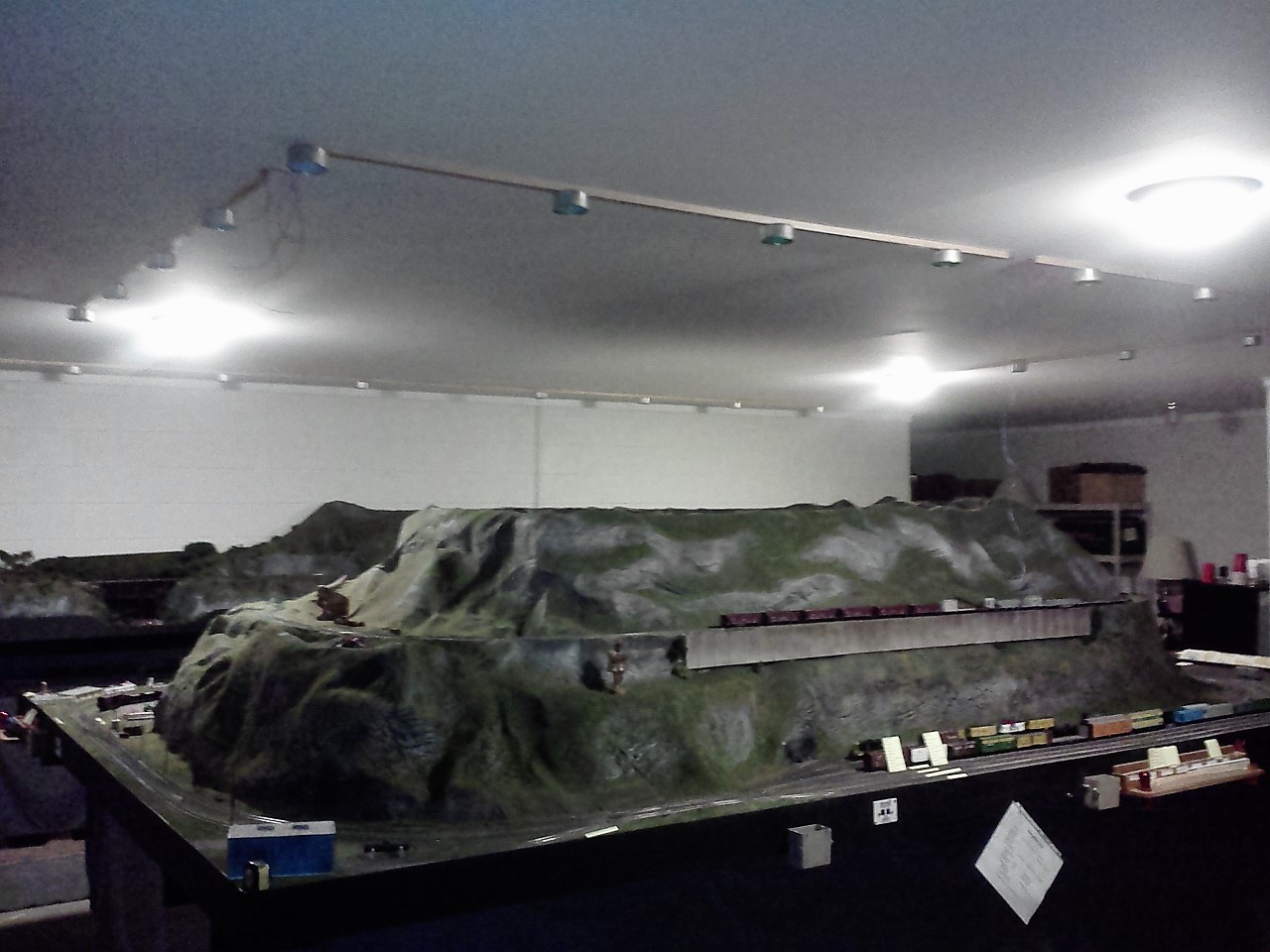
The last set went up over the main part of the room. The wires were not hooked up at this time and on the corners the wires are hanging down. The 18w LEDs are lighting up the room. Three lights will not cover all of the layout that you see. A u-shape was formed with the lights to complete the coverage needed to see the couplers on the cars on the track below.
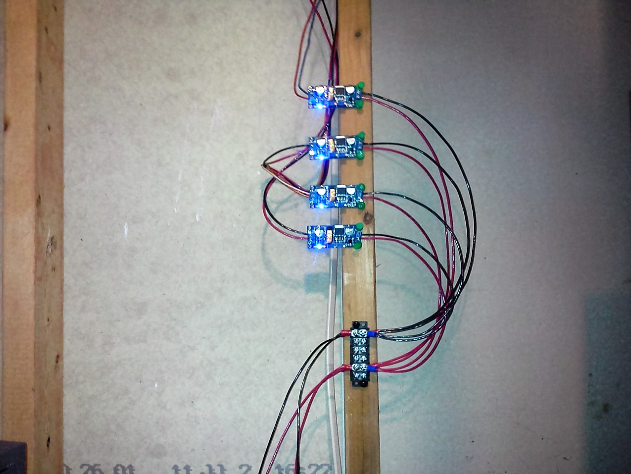
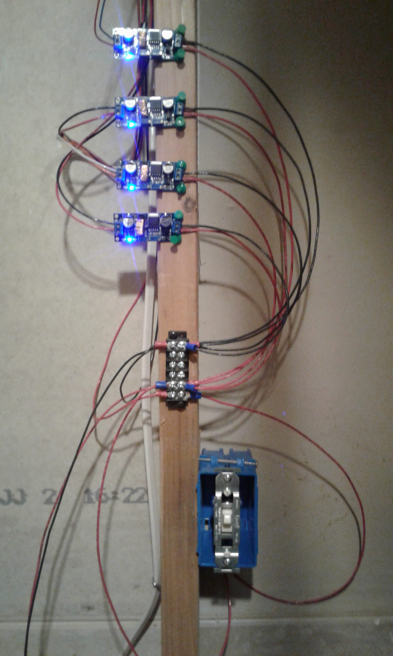
I used four battery chargers called buck drivers to power up the lights. The settings are as follows: The Amps are set to .6A on the driver and the voltage was set to 12V. ( the voltage must be lowered to set the amperage and then raised back up). Each driver will power-up 16 – 3W LED bulbs in sets of four. The four drivers in the photo will power a total of 64 3w LED bulbs. That many lights will light up the entire layout. One more has been added for the lights at the station.
I used a Gopro camera to take the photo. With all the lights on, it’s hard to think that I’m using 1/4 the wattage than before the LED’s were installed.
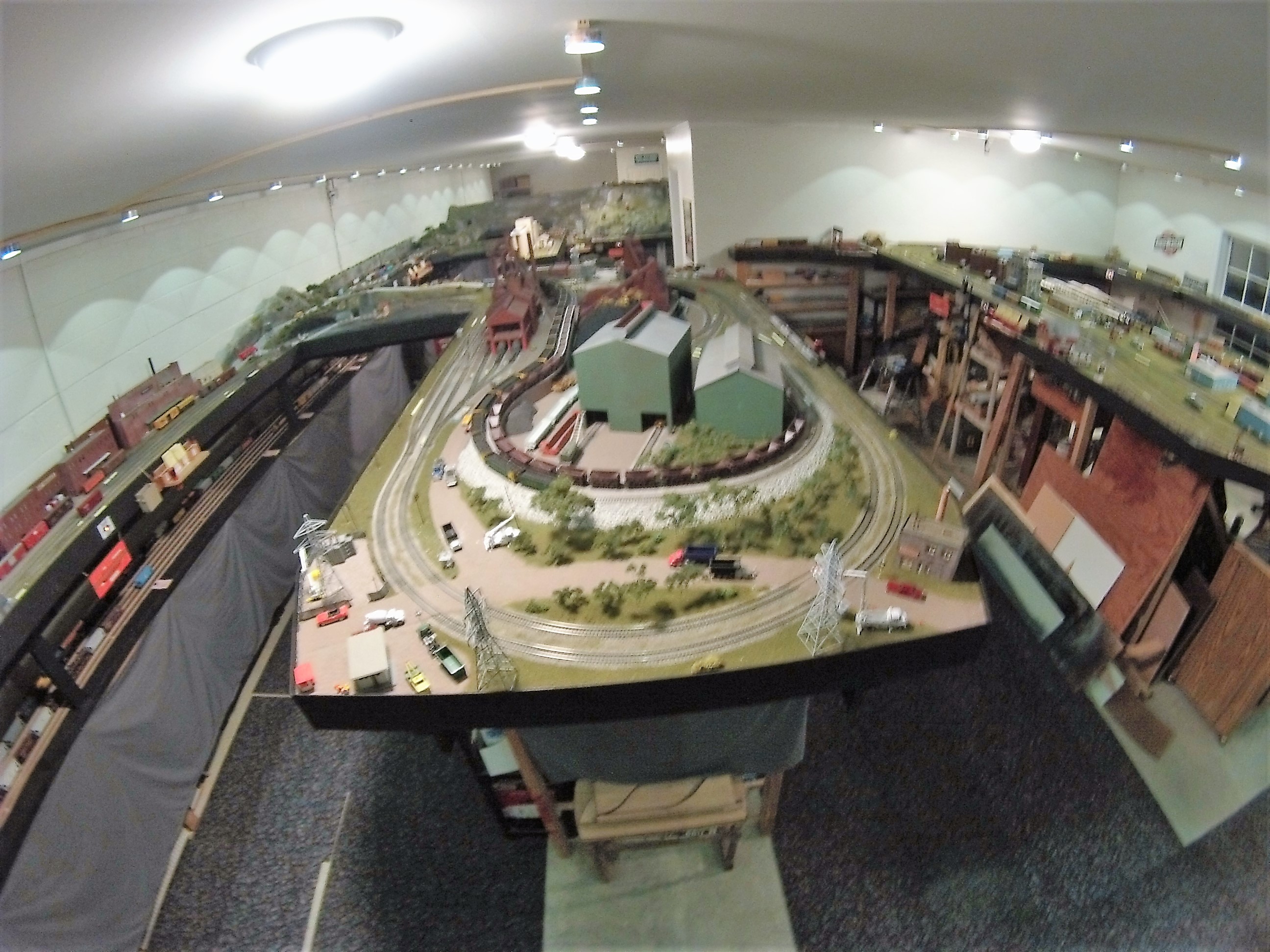
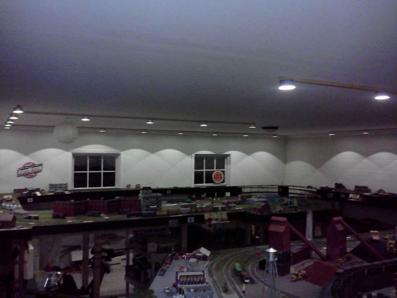
This is just another angle to show the lighting over the railroad.
Hope you like the changes in the lighting and hope this helps you find a better way to light your layout up.
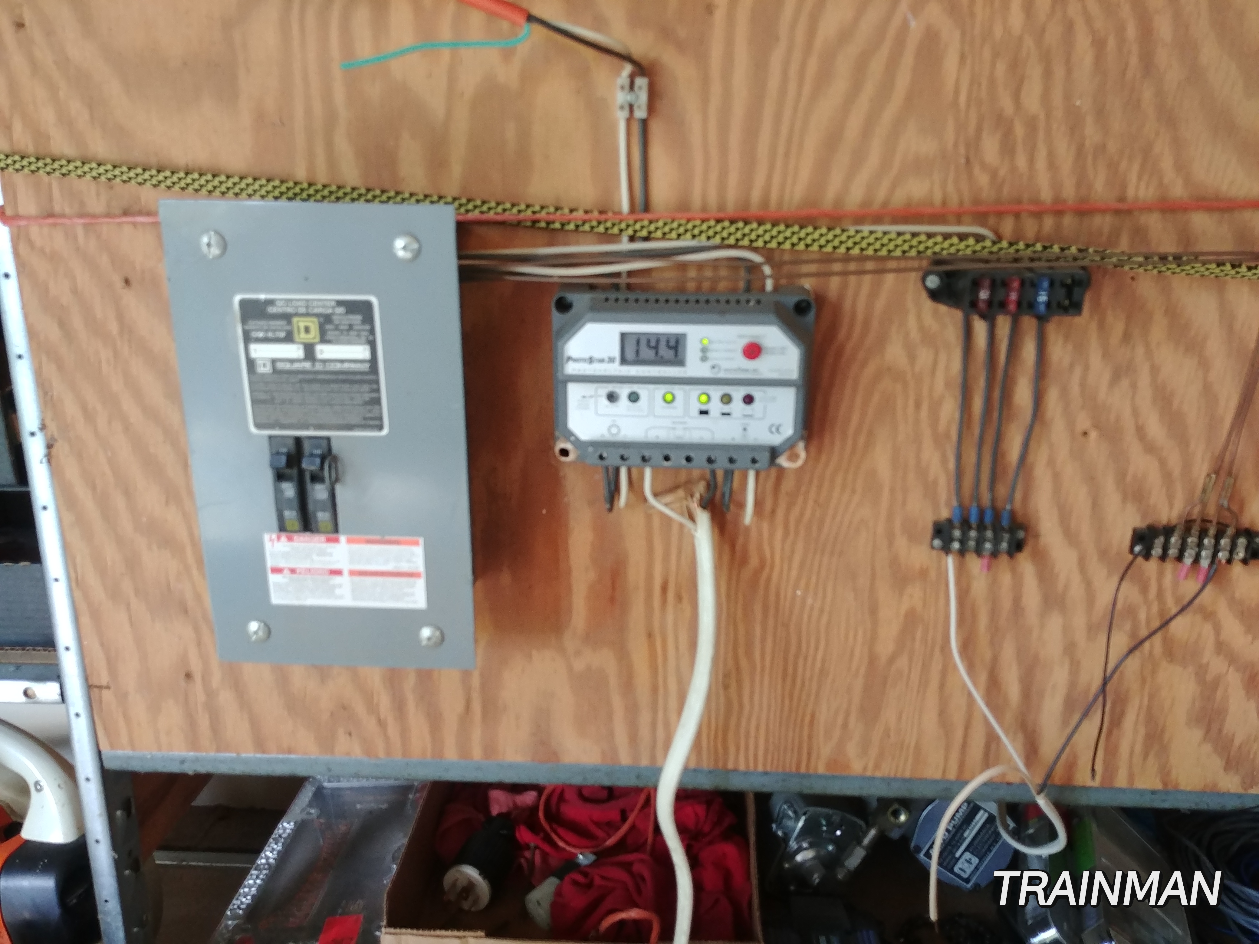
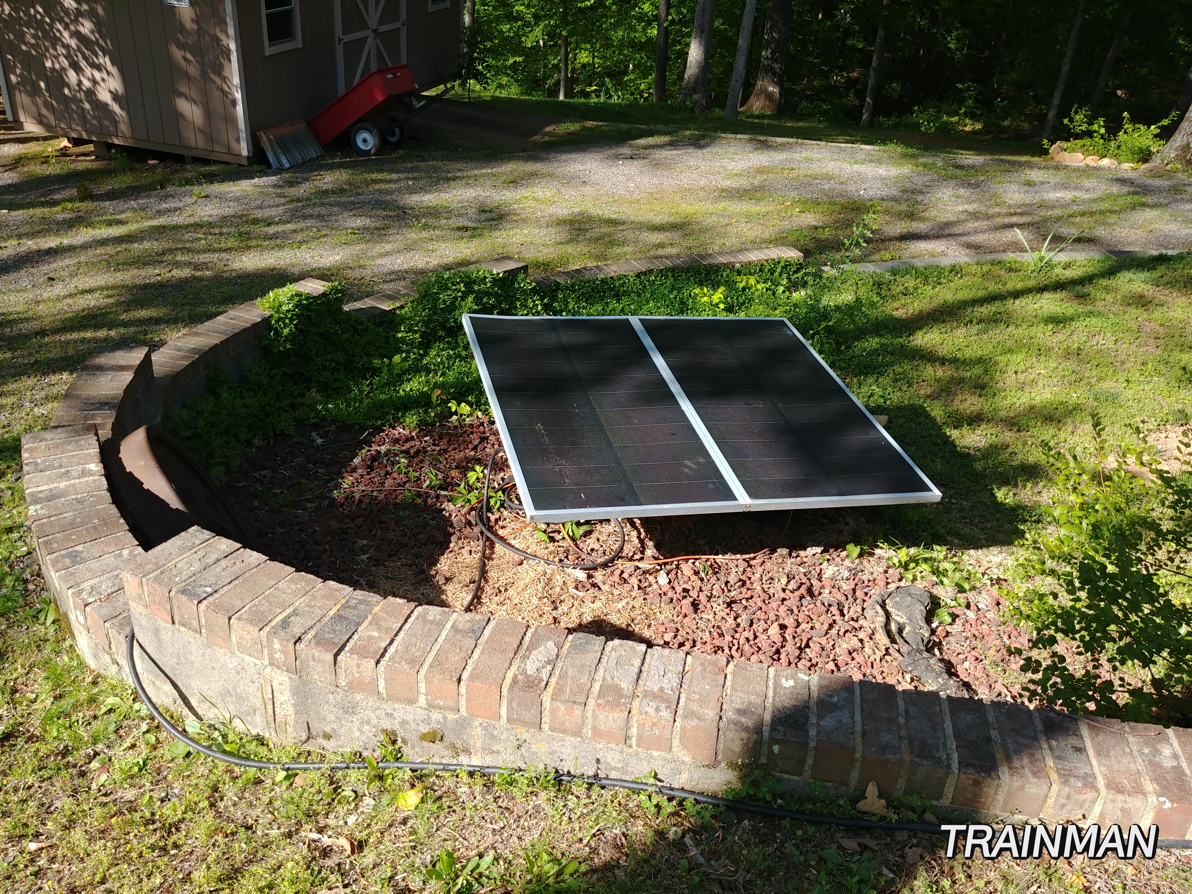
The solar panels are hooked up and running the can lights in the basement.
Only took 14 years to get the power and the lights hooked up. lol
The amp gauge said that I’m pulling 1.2 amps running the lights.
Thank You for looking at my story.
Download “Improving Lighting in your Layout Room” by Neal Anderson